In this blog post, I will talking about a stepper motor and will be interfacing it with the DSPIC30F4011.
A stepper motor is a brushless DC motor that divides a full rotation into a number of steps. The stepper motor we will be using for this module is the 28BYJ-48 which we will be operating at 5V. Each “Step” is basically a magnetic coil within the motor turning on, as the coil turns on the within the stator, the magnetic field created by the stator turns the rotor, as the rotor turns the next step is made by simply turning off another coil within the stator and off the previous coil. In this circuit diagram and image below show a perfect example of how the coils are wired and how the rotor turns within the motor. The circuit diagram below shows a total of four coils, however, these four coils are only there to represent the circuit electrically, the stator its self is made of many of these “single coils”, the GIF image below shows these coils magnetic field rotating.
This allows for great control as small degree’s of movement can be made with this motor
Typically due to the fact, the dspic cannot feed a high enough level for current to move motors, the SN754410NE driver chip will be used once again to drive the stepper motor, very similar to how the DC motor works.
Operational Code
// Written by Kevin T
// Code Written on the 16/12/16
// Based on the code written from Ted Burke
// @batchloaf.wordpress.com or @roboted.wordpress.com

#include <xc.h>
#include 			<libpic30.h>
#include <time.h>

//definitions
#define STEP_DELAY 65000

// Configuration settings
_FOSC(CSW_FSCM_OFF & FRC_PLL16); // Fosc=16x7.5MHz, i.e. 30 MIPS
_FWDT(WDT_OFF); // Watchdog timer off
_FBORPOR(MCLR_DIS); // Disable reset pin

//functions must FUNCTION
void full_step_forward();
void full_step_backward();
void half_step_forward();
void half_step_backward();
void steps();

int main()
{
int n = 0;

//configure digital I/O
TRISD = 0b0000; // one digital output for each winding
LATD = 0b0001; // all windings off to start with

while(1)
{
n = n + 1;
if      (n <= 1 ) full_step_forward(); else if (n >= 1 ) full_step_backward();
else if (n <= 2 ) half_step_forward(); else if (n >= 2 ) half_step_backward();
else n = 0;
}

return 0;

}

void half_step_forward()
{
if      (LATD == 0b0001) LATD = 0b1001;
else if (LATD == 0b1001) LATD = 0b1000;
else if (LATD == 0b1000) LATD = 0b1100;
else if (LATD == 0b1100) LATD = 0b0100;
else if (LATD == 0b0100) LATD = 0b0110;
else if (LATD == 0b0110) LATD = 0b0010;
else if (LATD == 0b0010) LATD = 0b0011;
else                     LATD = 0b0001;

__delay32(STEP_DELAY);
}

void full_step_forward()
{
if      (LATD == 0b0001) LATD = 0b1000;
else if (LATD == 0b1000) LATD = 0b0100;
else if (LATD == 0b0100) LATD = 0b0010;
else                     LATD = 0b0001;

__delay32(STEP_DELAY);
}

void half_step_backward()
{
if      (LATD == 0b0001) LATD = 0b0011;
else if (LATD == 0b0011) LATD = 0b0010;
else if (LATD == 0b0010) LATD = 0b0110;
else if (LATD == 0b0110) LATD = 0b0100;
else if (LATD == 0b0100) LATD = 0b1100;
else if (LATD == 0b1100) LATD = 0b1000;
else if (LATD == 0b1000) LATD = 0b1001;
else                     LATD = 0b0001;

__delay32(STEP_DELAY);
}

void full_step_backward()
{
if      (LATD == 0b0001) LATD = 0b0010;
else if (LATD == 0b0010) LATD = 0b0100;
else if (LATD == 0b0100) LATD = 0b1000;
else                     LATD = 0b0001;

__delay32(STEP_DELAY);
}
Unfortunately, my code does not transition between direction very quickly this video has been brought up to twice the original speed of the video recorded, so please do skip to 0:35, 1:10, 1:45, and 2:20 to see the direction change. And yes I did record that video for 5 minutes I would of speed up the video a bit more, however, my phone only allows me to speed it up to twice the speed max, hopefully, the background music. enjoy!
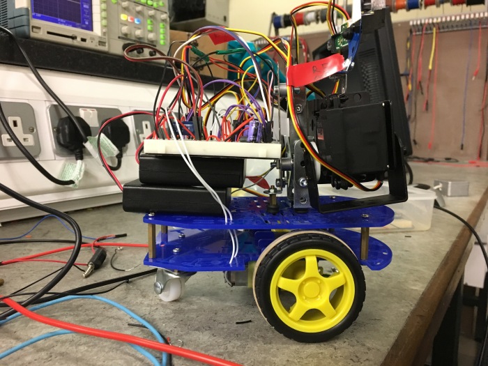
For my mini-project, I have decided to create a simple bodyguard robot. Its main functions are protect something in a certain place area and if someone were to come close to that area the robot will try to prevent you from entering that area.
All my previous codes were built and designed to work with the final mini-project.
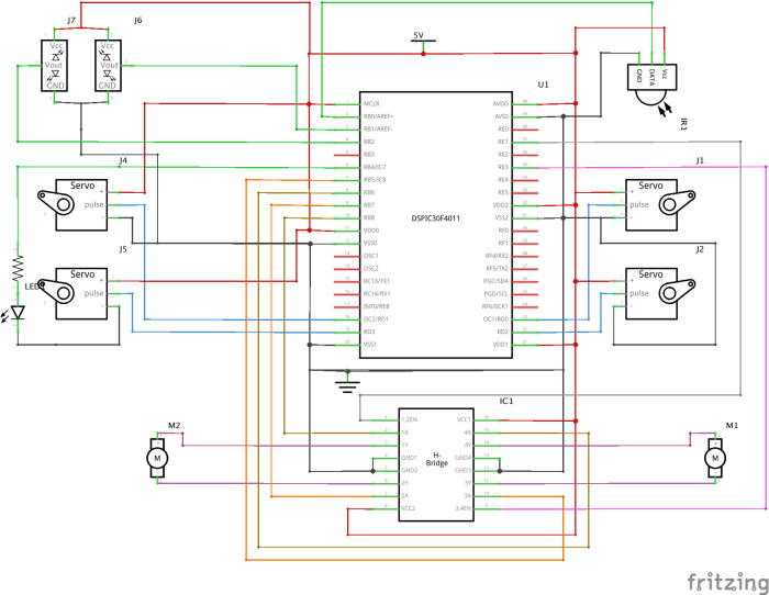
The construction of the robot uses two pan and tilt servo motor kits which were purchased from the robotshot.com and a few other parts to keep the whole system together.
Movement of the arms (servo motors) are controlled by the output compare [OC1 – OC4] module within the DSPIC main reason why I swapped from the PWM channels to the output compare was I had 4 servo motors to be used and only 3 PWM channels, also I had two motors that needed to be used for PWM to vary the speed at which they turn. So the best and efficent way of controlling the servo motors was with the output compare module located on all 4 RD pins, the motors, and the LED are controlled by RB pins configured in digital output mode [RB5 – RB9], while the IR range sensors the ADC [AN1 – AN2].
This slideshow requires JavaScript.
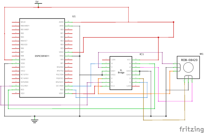
Circuit Diagram
Although the circuit diagram above shows that there is an IR colour sensor, in the end, I wasn’t able to add it to follow or detect white lines on the ground, this was due to time constraints however in the future I plan to continue to upgrade this robot with more features.
Power Issue
After the robot was constructed both mechanically and electrically one noticeable problem after uploading the code onto the DSpic was that the robot was restarting very frequently. After setting up an oscilloscope and applying it across the voltage rail, it was noted that voltage was not stable due to power consumption from all the motors (a total of 6). So quick fix to allow for the voltage not to drop below 5volts and resetting the DSpic was to add another battery pack, in parallel (so that voltage doesn’t double but the current). With more current carrying capacity from the voltage source, the voltage rail was stable and the robot functioned without resetting.
Possible States
In this code, I did not use a state machine as I felt there wasn’t a need to however, there are 4 possible actions coming from the bodyguard robot I have listed them down below.
State
Action
Actuators
State Transition
1
Move Forward
Arms down
Left & Right Motor Forward
Left & Right Arms Down
If Right & Left Range Finder Are within Threshold move to state 2
If Right Range Finder is within Threshold move to state 3
If Left Range Finder is within Threshold move to state 4
2
Full Stop
Both Arms Up
Left & Right Motor Fully Stop
Left & Right Arms up
If Right Range Finder is within Threshold move to state 3
If Left Range Finder is within Threshold move to state 4
If Left & Right Range Finder are not within Threshold move to state 1
3
Turn Right
Right Arm Up
Right Motor Forward Left Motor Stop
Right Arm up Left Arm Down
If Right & Left Range Finder Are within Threshold move to state 2
If Left Range Finder is within Threshold move to state 4
If Left & Right Range Finder are not within Threshold move to state 1
4
Turn Left
Left Arm Up
Left Motor Forward Right Motor Stop
Left Arm up Right Arm Down
If Right & Left Range Finder Are within Threshold move to state 2
If Right Range Finder is within Threshold move to state 3
If Left & Right Range Finder are not within Threshold move to state 1
Code that runs this contraption
// Final Code that makes the body move forward, turn left or right
// depending on what the two range finder sensors see individually
// last updated 11-1-2017
// Written by Kevin Tighe
// code based on Batchloaf/Roboted.wordpress.com by Ted Burke

//important stuff
#include <xc.h>
#include <libpic30.h>

//Hash_define
#define Second 30000000

//More important stuff
_FOSC(CSW_FSCM_OFF & FRC_PLL16); // Clock speed = 7.5MHz x 16, i.e. 30 MIPS
_FWDT(WDT_OFF);                  // Watchdog timer off
_FBORPOR(MCLR_DIS);              // Disable reset pin

//Functions
unsigned int read_analog_channel(int channel);
void SetArmPositionLeft();
void SetArmPositionRight();
void Backward();
void Left();
void Right();
void Stop();

int main(void)
{
     // Configure RB pins to be digital and Analogue
    ADPCFG = 0b11111000;

    // Configure AN0as analog inputs
    ADCON3bits.ADCS = 15;  // Tad = 266ns, conversion time is 12*Tad
    ADCON1bits.ADON = 1;   // Turn ADC ON

    // Make RB4 and RD8 digital outputs;
    LATB = 0;
    TRISB = 0b000001111;

    // Configure Timer 2 (default timer for output compare)
    T2CONbits.TCKPS = 0b10; // Timer 2 prescaler 1:64
    PR2 = 9375;             // Timer 2 period (20ms)
    T2CONbits.TON = 1;      // Enable Timer 2

    // Configure Output Compare channels
    OC1CONbits.OCM = 0b101; // continuous pulse mode
    OC1R = 0;               // pulse start time
    OC1RS = 703;            // pulse stop time
    OC2CONbits.OCM = 0b101;
    OC2R = 0;
    OC2RS = 703;
    OC3CONbits.OCM = 0b101;
    OC3R = 0;
    OC3RS = 703;
    OC4CONbits.OCM = 0b101;
    OC4R = 0;
    OC4RS = 703;

    // Configure PWM
    // PWM period = PTPER * prescale * Tcy = 9470 * 64 * 33.33ns = 20ms
    _PMOD1 = 0; // PWM channel 3 mode: 0 for complementary, 1 for independent
    _PEN1H = 1; // PWM1H pin enable: 1 to enable, 0 to disable
    _PTCKPS = 3; // PWM prescaler setting: 0=1:1, 1=1:4, 2=1:16, 3=1:64
    PTPER = 9470; // Set PWM time base period to 20ms (15-bit value)
    PDC1 = 0; // 0% duty cycle on channel 1 (16-bit value)
    _PTEN = 1; // Enable PWM time base to start generating pulses

    int r;
    for(r=0 ; r<10 ; ++r)
    {
        _LATB4 = 1;
        __delay32(1500000);
        _LATB4 = 0;
        __delay32(1500000);
    }

    // Configure max and min OC1RS values
    int min = 260;  // OC1RS value for 0 degrees
    int max = 1070; // OC1RS value for 180 degrees

    // An Array of angles for arm movement.
    //                            0      1      2      3      4      5      6      7      8     9     10     11     12     13     14     15     16     17     18
    float LeftShoulder  [] = {  0.0,  10.0,  20.0,  30.0,  40.0,  50.0,  60.0,  70.0,  80.0, 90.0, 100.0, 110.0, 120.0, 130.0, 140.0, 150.0, 160.0, 170.0, 180.0};
    float LeftElbow     [] = {  0.0,  10.0,  20.0,  30.0,  40.0,  50.0,  60.0,  70.0,  80.0, 90.0, 100.0, 110.0, 120.0, 130.0, 140.0, 150.0, 160.0, 170.0, 180.0};
    float RightShoulder [] = {180.0, 170.0, 160.0, 150.0, 140.0, 130.0, 120.0, 110.0, 100.0, 90.0,  80.0,  70.0,  60.0,  50.0,  40.0,  30.0,  20.0,  10.0,   0.0};
    float RightElbow    [] = {180.0, 170.0, 160.0, 150.0, 140.0, 130.0, 120.0, 110.0, 100.0, 90.0,  80.0,  70.0,  60.0,  50.0,  40.0,  30.0,  20.0,  10.0,   0.0};

    int threshold  = 256;
    //int threshold2 = 256

    while(1)
    {
        if      (read_analog_channel(1) < threshold && read_analog_channel(2) < threshold)
        {
        Right();
        Left();
        SetArmPositionRight(RightShoulder[0], RightElbow[7]);
        SetArmPositionLeft(LeftShoulder[0], LeftElbow[7]);
        __delay32(Second/10);
        }
        else if (read_analog_channel(1) > threshold && read_analog_channel(2) > threshold)
        {
            _LATB4 = 1;
            SetArmPositionRight(RightShoulder[12], RightElbow[10]);     //Right Arm up
            SetArmPositionLeft(LeftShoulder[12], LeftElbow[10]);        //Left Arm up
            Stop();                                                     //Stop Both Motors
            __delay32(Second/10);                                       //Delay to keep servo motors steady in position
        }

        else if (read_analog_channel(1) > threshold)                    //Right Sensor has detected something
        {
            SetArmPositionRight(RightShoulder[12], RightElbow[7]);      //Raise Right arm
            SetArmPositionLeft(LeftShoulder[0], LeftElbow[7]);
            Stop();
            Right();                                                    //Turn rightmotor to follow person
            __delay32(Second/10);
        }

        else if (read_analog_channel(2) > threshold)                    //Left Sensor has detected something
        {
            SetArmPositionRight(RightShoulder[0], RightElbow[7]);
            SetArmPositionLeft(LeftShoulder[12], LeftElbow[7]);         //Riase Left arm
            Stop();
            Left();                                                     //Turn leftmotor to follow person
            __delay32(Second/10);
        }
    }
}

//Arm Functions
void SetArmPositionLeft(double shoulder, double elbow)
{
    // Configure max and min OC1RS values
    int min = 260;  // OC1RS value for 0 degrees
    int max = 1070; // OC1RS value for 180 degrees

    OC1RS = min + (shoulder/180.0)*(max-min); // Left Arm
    OC4RS = min + (elbow/180.0)*(max-min);
}
void SetArmPositionRight(double shoulder, double elbow)
{
     // Configure max and min OC1RS values
    int min = 260;  // OC1RS value for 0 degrees
    int max = 1070; // OC1RS value for 180 degrees

    OC2RS = min + (shoulder/180.0)*(max-min);// Right Arm
    OC3RS = min + (elbow/180)*(max-min);
}

//Motor Functions
void Stop()
{
    _LATB5 = 0;
    _LATB6 = 0;
    _LATB7 = 0;
    _LATB8 = 0;
}

void Right()
{
    _LATB5 = 1;
    _LATB6 = 0;
    PDC1 = 0.9 * 2 * PTPER;     // 90% duty cycle
}

void Left()
{
    _LATB7 = 1;
    _LATB8 = 0;
    PDC1 = 0.9 * 2 * PTPER;     // 90% duty cycle
}

// This function reads a single sample from the specified
// analog input. It should take less than 5us when the
// microcontroller is running at 30 MIPS.
// The dsPIC30F4011 has a 10-bit ADC, so the value
// returned is between 0 and 1023 inclusive.
unsigned int read_analog_channel(int channel)
{
    ADCHS = channel;          // Select the requested channel
    ADCON1bits.SAMP = 1;      // Start sampling
    __delay32(30);            // 1us delay @ 30 MIPS
    ADCON1bits.SAMP = 0;      // Start Converting
    while (!ADCON1bits.DONE); // Should take 12 * Tad = 3.2us
    return ADCBUF0;
}
A selection of videos of the robot operational to the build Enjoy!
As part of Robotics 3.1 Module, I have been given the task of operating a few actuators with the DSPIC30F4011. The DSPIC30F series is a 16-bit signal controller that allows for both Pulse Width Modulation (PWM) for motor control and analog and digital inputs that can be used for control mechanisms or some really awesome robotic projects. A pickit2 is the medium device used to connect to the DSpic30 to the PC to program it. The pickit2 can power up the DSPIC however due to safety mechanisms or maximum current output from the pickit there will be moments where the I will have to use the battery pack provided to power up the system, an example of this would be when motors are used due to the level of current that is needed to produce torque.
Text Editor
It was recommended to use Notepad ++ which is installed in most of the computers in college however, due to my experience in web development I’ve decided to stick with using Subline Text as I found it a great text editor to use, theoretically it does not matter what type of text editor you use to write any computer code language, however with its simplicity and features I personally have found it handy in helpful when debug code.
Compiler
The compiler used to convert the c-code into machine code was the xc compiler which is downloadable for free.
In this blog, I will be talking about what a servo motor is and how it operates.
A servo motor is an actuator that allows for high degree control of angles between 0 and 90 degree’s (depending on the “range” of the specific motor it could be greater), this is a level of control is achieved due to its design which can be explained in great detail the following video.
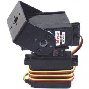
A servo motor as shown in the picture below is controlled by a length of a pulse generated from a microcontroller.
PWM (Pulse Width Modulation) as I have mentioned in my previous blog can be used in many applications. In this scenario, we will be using PWM to control the angle of a servo motor. The minimum pulses being 0 and highest normally being 2 ms. In some servo motors the upper limit and angle will be greater than 180 degrees and 2 ms.
For my mini-project, I intend to make a simple bodyguard robot that has two arms and moves around on wheels. Since two arms are required I decided to use 2 servo motors per arm in a pan and tilt configuration.
with a bit of googling, I stumped upon this.
CLICK ME!
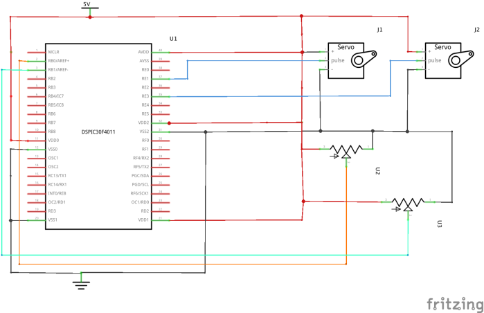
So I decided to buy 2 sets of these arms and a dual bracket to hold them together to act as the torso of the robot. Using two the PWM channels on the DSPIC30F4011, the ADC, and a potentiometer. I used a code to see the limitations of the motors angles.
When the kit arrived, construction began.
// Written by Kevin Tighe
// Based on the code written by Ted Burke
//@batchloaf.wordpress.com or @roboted.wordpress.com
// Last updated 11/12/2016
//

#include <xc.h>
#include 			<libpic30.h>
#include <stdio.h>

// Configuration settings
_FOSC(CSW_FSCM_OFF & FRC_PLL16); // Fosc=16x7.5MHz, i.e. 30 MIPS
_FWDT(WDT_OFF); // Watchdog timer off
_FBORPOR(MCLR_DIS); // Disable reset pin

//definitions
#define Second 30000000 // 1 second

// Function prototypes
unsigned int read_analog_channel(int n);

int main()
{
int voltage = 0;
int voltage2 = 0;
// Make all port D pins outputs
TRISD = 0;

// Configure AN0-AN8 as analog inputs
ADCON3bits.ADCS = 15; // Tad = 266ns, conversion time is 12*Tad
ADCON1bits.ADON = 1; // Turn ADC ON

// Configure PWM for free running mode
//
// PWM period = Tcy * prescale * PTPER = 0.33ns * 64 * PTPER
// PWM pulse width = (Tcy/2) * prescale * PDCx
//
PWMCON1 = 0x00FF; // Enable all PWM pairs in complementary mode
PTCONbits.PTCKPS = 3; // prescale=1:64 (0=1:1, 1=1:4, 2=1:16, 3=1:64)
_PEN2H = 1; // Enable PWM1H pin
_PEN2L = 1; // Enable PWM1L pin
PTPER = 9375; // 20ms PWM period (15-bit period value)
PDC1 = 1406;
PDC2 = 1406; // 1.5ms pulse width on PWM channel 1
PDC3 = 1406;
PTCONbits.PTEN = 1; // Enable PWM time base

// Setup UART
U1BRG = 48; // 38400 baud @ 30 MIPS
U1MODEbits.UARTEN = 1; // Enable UART

// fast flsh to signal reset
int n;
for(n=0;n<10;n++) //Small tester code to see if LED / Circuit is working
{
_LATD1 = 1;
__delay32(1500000);
_LATD1 = 0;
__delay32(1500000);
}

while(1)
{
// Read analog voltage from AN0 (pin 2)
// The number returned (between 0 and 1023)
// represents a voltage in the range 0-5V.
voltage = read_analog_channel(0);
voltage2 = read_analog_channel(1);

// If the voltage is greater than 2.5V
// turn on the LED on RD0 (pin 23),
// otherwise turn it off.
if (voltage < 512) _LATD0 = 0;
else _LATD0 = 1;

// Display the voltage reading on screen
printf("\nVoltage = %d\n\n\n", voltage);
printf("\nVoltage2 = %d\n", voltage2);

// Calculate and update the servo angle
// based on potentiometer voltage on AN0.
// In this case we want voltage values
// between 0 and 1023 to be mapped onto
// PDC1 values between 600 and 1800.
PDC2 = 500 + (2000-500)*(voltage/1023.0);
PDC3 = 425 + (1500-450)*(voltage2/1023.0);
// 100ms delay
__delay32(Second/10);
}

return 0;
}
// This function reads a single sample from the specified
// analog input. It should take less than 5us when the
// microcontroller is running at 30 MIPS.
// The dsPIC30F4011 has a 10-bit ADC, so the value
// returned is between 0 and 1023 inclusive.
unsigned int read_analog_channel(int channel)
{
ADCHS = channel; // Select the requested channel
ADCON1bits.SAMP = 1; // Start sampling
__delay32(30); // 1us delay @ 30 MIPS
ADCON1bits.SAMP = 0; // Start Converting
while (!ADCON1bits.DONE); // Should take 12 * Tad = 3.2us
return ADCBUF0;
}

Here's a small video of the progression that was made.
In this blog post I will cover the operation of a DC motor with PWM control.
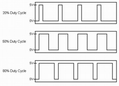
PWM stands for “Pulse Width Modulation” and is a very handy tool in electronics and robotics. It can be used to dim an LED (by adjusting the average voltage [also known as the duty cycle, I’ll place some equations about how that relates]) it can also be used to control the angle of a servo motor depending on the “Time” of the pulses being produced by the micro-controller.
Now back to the DC motor and its control, based on my last blog we saw we can control motor in three different states [Forward, Backwards, and no where (if I ever edit the code I’ll add the stop position in that code)]. Now we are going to add a control method of accelerating the motor between different speeds. We will send a PWM signal in different duty cycles from the DSPIC30F4011 to the SN754410NE driver chip.
As the SN754410NE datasheet states it has a “1, 2EN and 3, 4EN” on pins 1 and 9. These pins will be used to input the PWM signal from the DSpic. In this scenario 25% duty cycle means 1/4th of the full speed, 50% duty cycle means 1/2 the full speed, 75% means 3/4 the full speed, and 100% duty cycle means full speed. So by having the motor move in a certain direction added with a PWM duty cycle we will have a motor moving in one direction at any given speed.
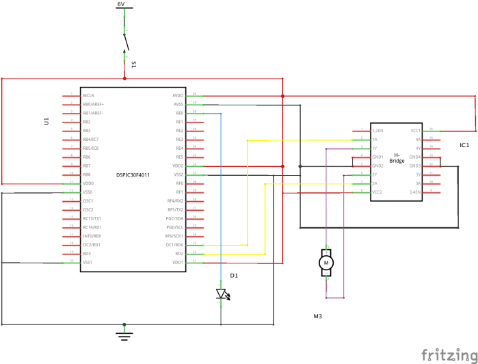
Here is the code used for the video sample below.
//
// DC Motor control example for dsPIC30F4011
// Written by Kevin Tighe
// Based on the code written by Ted Burke
// Last updated 28-10-2016
//

//important stuff
#include <xc.h>
#include 				<libpic30.h>
#include <stdio.h>
//More important stuff
_FOSC(CSW_FSCM_OFF & FRC_PLL16); // Clock speed = 7.5MHz x 16, i.e. 30 MIPS
_FWDT(WDT_OFF); // Watchdog timer off
_FBORPOR(MCLR_DIS); // Disable reset pin

//definitions

#define Second 30000000

int main(void)

{
// Make All D pins digital outputs
TRISD = 0b0000;

// Configure PWM
// PWM period = PTPER * prescale * Tcy = 9470 * 64 * 33.33ns = 20ms
_PMOD1 = 0; // PWM channel 3 mode: 0 for complementary, 1 for independent
_PEN1H = 1; // PWM1H pin enable: 1 to enable, 0 to disable
_PTCKPS = 3; // PWM prescaler setting: 0=1:1, 1=1:4, 2=1:16, 3=1:64
PTPER = 9470; // Set PWM time base period to 20ms (15-bit value)
PDC1 = 0; // 0% duty cycle on channel 1 (16-bit value)
_PTEN = 1; // Enable PWM time base to start generating pulses

// Control motor
while(1)
{
// Forward for 4 seconds @ 10% Power
PDC1 = 0.1 * 2 * PTPER;     // 10% duty cycle
LATD = 0b0011;                    // Forward & LED ON
__delay32(Second * 4);

//Forward for 4 seconds @ 25% Power
PDC1 = 0.25 * 2 * PTPER;      // 25% duty Cycle

LATD = 0b0011;                       // Forward & LED ON
__delay32(Second * 4);

//Backward for 4 seconds @ 50% Power
PDC1 = 0.50 * 2 * PTPER;     // 50% duty Cycle

LATD = 0b0100;                      // Backword & LED OFF
__delay32(Second * 4);

//Forward for 4 seconds @ 75% Power
PDC1 = 0.75 * 2 * PTPER;        // 75% duty cycle

LATD = 0b0011;                          // Forward & LED ON
__delay32(Second* 4);

//Forward for 4 seconds @ 25% Power
PDC1 = 1 * 2 * PTPER; // 100% duty cycle

LATD = 0b0
__delay32(Second* 4);

// Stop for 2 seconds
LATD = 0b0010;
PDC1 = 0 * 2 * PTPER; // 25% duty cycle
__delay32(Second * 2);
}
}
As some of you may have noticed I did use a 20 Volt power supply in the video, the main reason for this was at 6 volts I could not get the level of current to drive the motor at higher speeds, its also fun to watch things move fast. Any ways the motor did not move very well with low duty cycles at 6 Volts so I thought 20 Volts was a great idea (since the maximum voltage the driver chip is only 32 Volts DC), another great aspect of higher torque is you can hear the motor changing speeds very well.
ON A SEPARATE NOTE:
I did a quick experiment with 30 volts (since the bench supply unit I had with me at the time could only go up to 30 Volts max), unfortunately I did not record but the motor moving at those speeds… Then my capacitor blew as you can see below it was not a bad explosion, should of used bigger capacitors.
if your wondering which one blew, look at the right one.
A DC motor is a type of electrical machine that uses Direct Current to rotate the shaft either clock wise or anti clock wise depending on the polarity applied to the motor.
A simple DC motor
The basic principal of operation for a DC motor is when current flows through the armature the electric field of the armature experiences a torque from the magnetic field caused by the rotor thus causes the armature to turn depending on the direction on which the current is flowing through the armature.
Since we know the current is proportional to the magnetic flux and torque, we can use this aspect of the motor ton control the speed of the motor, however the DSPIC30F4011 cannot supply enough current to even make the motors turn slightly, so a “driver chip” is needed, to produce the current levels to make the motor spin. SN754410NE quad half H-bridge IC will be used.
The SN75441one job is basically take in a logic instruction (ON or OFF) into its input pins from the DSPIC and produce that same logic instruction on its output pins with greater current levels than to that which the DSPIC can produce to help create the desired torque for the DC motor.
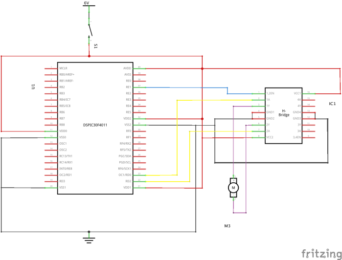
First lets start with ON and OFF control of the DC motor to create some simple forwards and backward motion. This Circuit diagram was created with “fritzing“.
//
// Single Motor On Off Control example for dsPIC30F4011
// Written by Kevin Tighe
// Based on the code written from Ted Burke
// @batchloaf.wordpress.com or @roboted.wordpress.com
//

//definitions
#define Second 30000000          // 1 second

//important stuff
#include <xc.h>
#include <libpic30.h>
#include <stdio.h>

//more important stuff
_FOSC(CSW_FSCM_OFF & FRC_PLL16); // Clock speed = 7.5MHz x 16, i.e. 30 MIPS
_FWDT(WDT_OFF);                  // Watchdog timer off
_FBORPOR(MCLR_DIS);              // Disable reset pin

int main(void)
{
// Make RD0 and RD2 digital outputs
TRISD = 0b1010;
_TRISE0 = 0;                     // make RE a D/IO
// Control motor
while(1)
     {
        // Forward for 4 seconds
        LATD = 0b0001;          // forwards
        _LATE0 = 1;
        __delay32(Second * 4);

        // Backwaard for 4 seconds
        LATD = 0b0100;         // backwards
        _LATE0 = 0;
        __delay32(Second * 4);

      }
}
Here is a sample of the motor in operation, I realized after watching the video that I should have added a stop. Enjoy the video!


 These pins will be used to input the PWM signal from the DSpic. In this scenario 25% duty cycle means 1/4th of the full speed, 50% duty cycle means 1/2 the full speed, 75% means 3/4 the full speed, and 100% duty cycle means full speed. So by having the motor move in a certain direction added with a PWM duty cycle we will have a motor moving in one direction at any given speed.